 English
 中文简体
 Français
 русский
 Español
 عربى
Content
- 1 What Is a Power Capacitor?
- 2 The Five Power Capacitor Families and Where Each One Belongs
- 3 Film Versus Aluminum Electrolytic: What the Choice Really Costs
- 4 Eight Specifications to Verify Before You Release a Purchase Order
- 5 A Six-Step Selection Sequence That Works in Practice
- 6 What Manufacturing Depth Changes About the Answer
- 7 Frequently Asked Questions
Most power capacitor failures that land on a customer complaint desk are not random. They trace back to the same root cause: a specification sheet that matched on capacitance and rated voltage but said nothing useful about ripple current, hot-spot temperature, or the operating profile the part would actually see. A 40 µF, 450 V AC filter capacitor dropped into a circuit with twice its rated ripple current will fail early, and often well inside a quarter of its quoted life.
The notes below cover what these components do, how the main families differ, and which numbers to verify before a purchase order goes out. The audience is engineers and buyers sourcing film capacitors for motor drives, lighting ballasts, PFC panels, and household appliances.
What Is a Power Capacitor?
A power capacitor is a passive component that stores energy in an electric field and releases it on demand, built and rated for the voltage, current, and temperature conditions found in power conversion or power distribution circuits.
The difference from a signal-level capacitor is scale, not principle. A unit on a 690 V DC bus may carry 200 A of ripple current at 8 kHz. The same physical mechanism that decouples a 3.3 V logic rail becomes a thermal engineering problem once currents climb into the hundreds of amps, and once the dielectric has to survive years of switching transients without maintenance access.
In practice, a power capacitor performs one or more of five jobs:
- Energy buffering on a DC bus, holding voltage steady between switching events
- Filtering, diverting harmonic or high-frequency current away from the supply
- Power factor correction, supplying reactive current close to the load
- Snubbing, absorbing the voltage overshoot when a semiconductor turns off
- Pulse discharge, releasing stored energy in a very short burst
The Five Power Capacitor Families and Where Each One Belongs
Power capacitors are classified by circuit function rather than by shape: shunt and PFC units correct displacement, DC-Link units buffer a switching bus, AC filter units bypass harmonics, snubber units clamp switching transients, and pulse units deliver short bursts of energy.
| Family | Primary duty | Typical ratings | Common end use |
| Shunt / PFC | Displacement power factor correction | 0.4 to 1 kV, 5 to 50 kvar per step | Industrial panels, motor groups, plant distribution |
| DC-Link | Bus voltage buffering between stages | 450 to 1200 V DC, high ripple current | Inverters, drives, EV chargers, solar converters |
| AC filter | Harmonic current bypass | 250 to 690 V AC | Grid-tied converters, switch-mode power supplies |
| Snubber | dv/dt and overvoltage clamping | 630 to 2000 V, low inductance | IGBT modules, high-frequency bridges |
| Pulse | Short high-current discharge | kV range, low ESL construction | Lasers, welding, medical and research equipment |
Catalogue names confuse buyers more than the physics does. The same part can be sold as a shunt capacitor, a PFC capacitor, or a low-voltage power capacitor depending on which market the label was written for.
Power Factor Correction Capacitors
A PFC capacitor does not generate reactive energy. It supplies it near the load, which reduces what the utility feed has to carry and lowers the current drawn through cables and transformers. Sizing is mostly a matter of matching the step kvar to how the load actually varies, then checking the harmonic environment: once background distortion passes roughly 10 percent THD, a detuned reactor ahead of the bank is standard practice to keep harmonic current out of the capacitor.
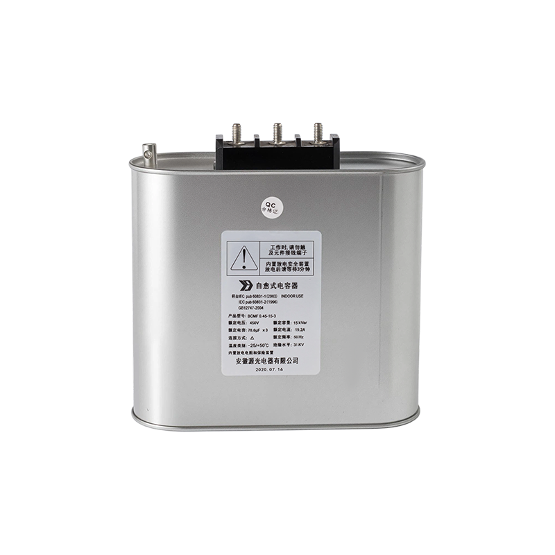
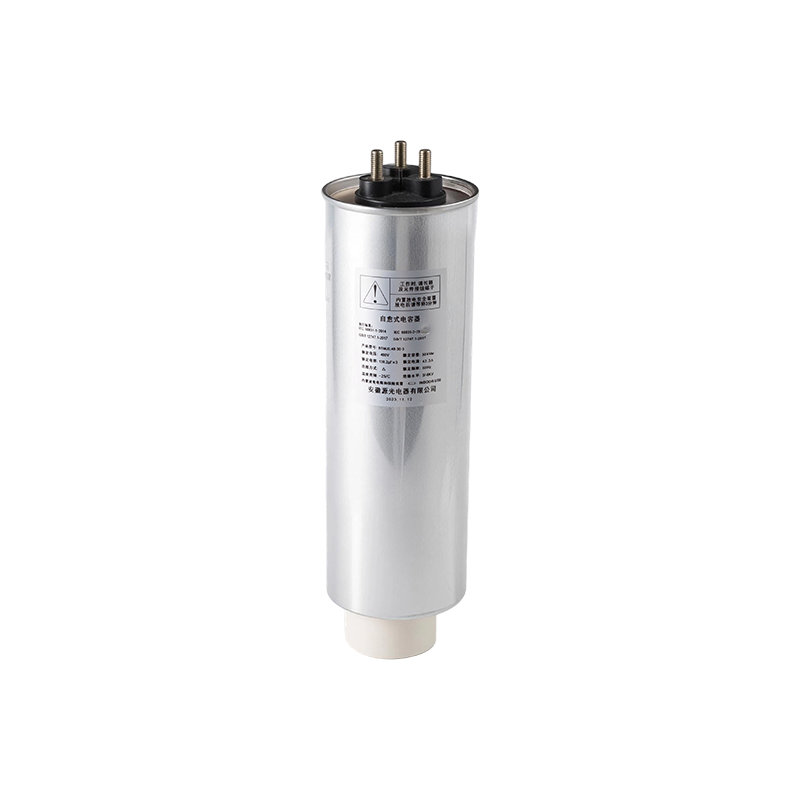
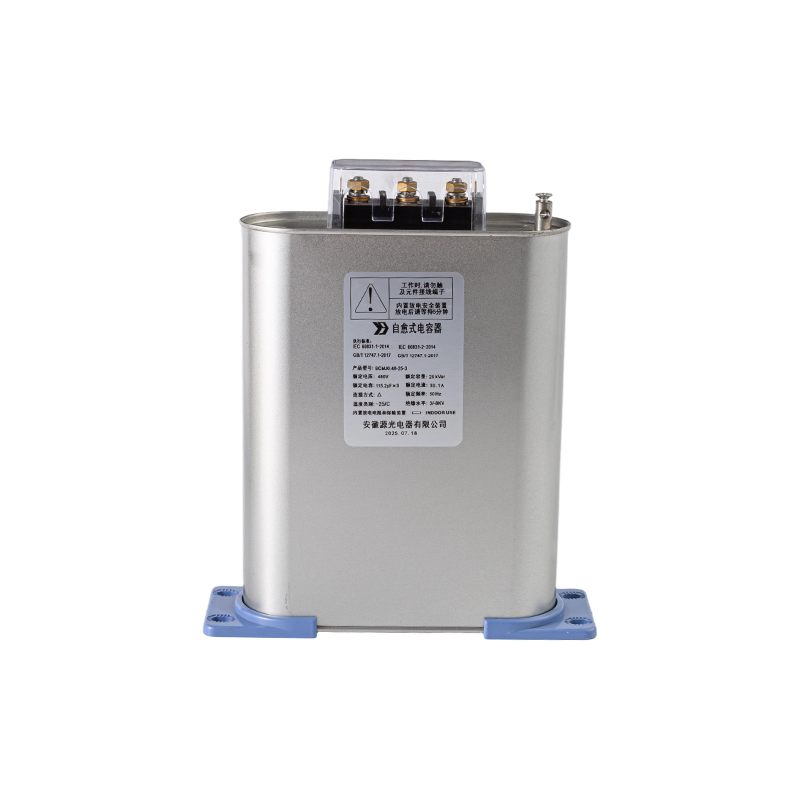
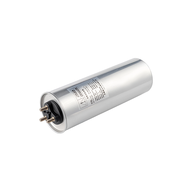 Low-Voltage PFC Shunt Power CapacitorsThree-phase cylindrical capacitors for power factor correction and filter circuits, with self-healing and over-pressure protection; relevant when sizing compensation banks and checking harmonic conditions.View Product →
DC-Link Capacitors
The DC-Link capacitor sits between the rectifier and the inverter stage, holding the bus steady while the switches pull current in short pulses. Its real enemy is ripple-current heating. Rated life is quoted at hot-spot temperature, not ambient, so the useful comparison between two candidates is the projected hot-spot under your actual load profile rather than the headline lifetime figure on the front of the datasheet.
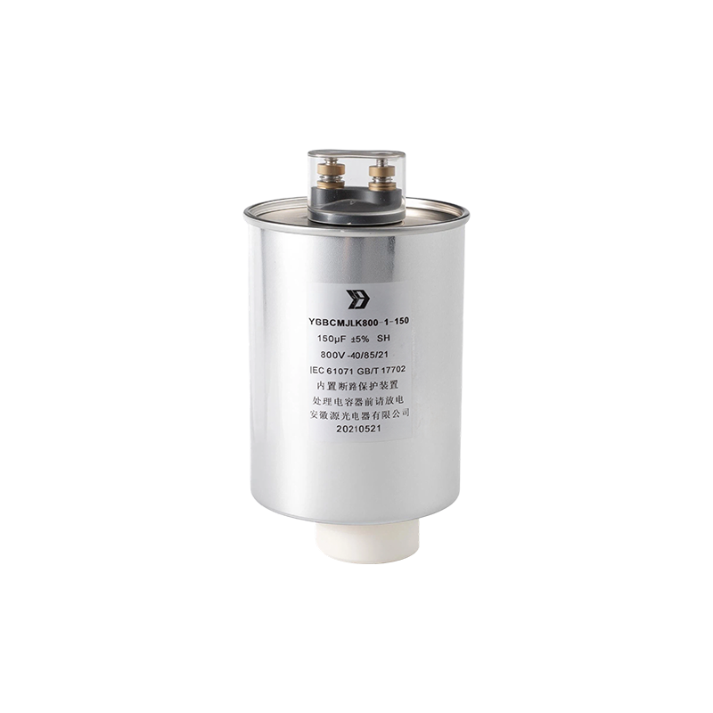
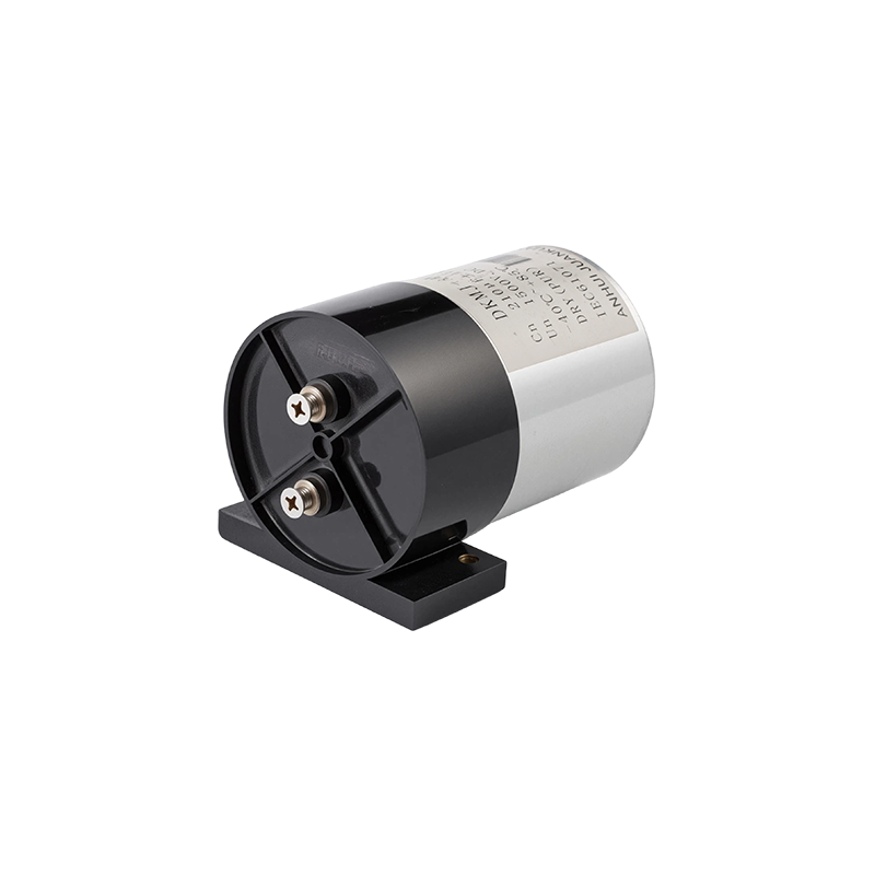 Dry Aluminium-Case DC-Link Power CapacitorsMetallized film DC-link capacitors with low ESR and high ripple-current capability, suited to inverter and EV applications where hot-spot heating under actual load matters.View Product →
AC Filter Capacitors for PCB and Panel Mounting
Filter capacitors divert harmonic current before it reaches the supply. On power supplies and small drives the part is usually a PCB-mount metallized polypropylene unit; on larger systems it moves into a dry or oil-filled aluminium case with terminals sized for the full line current and a thermal path built into the housing.
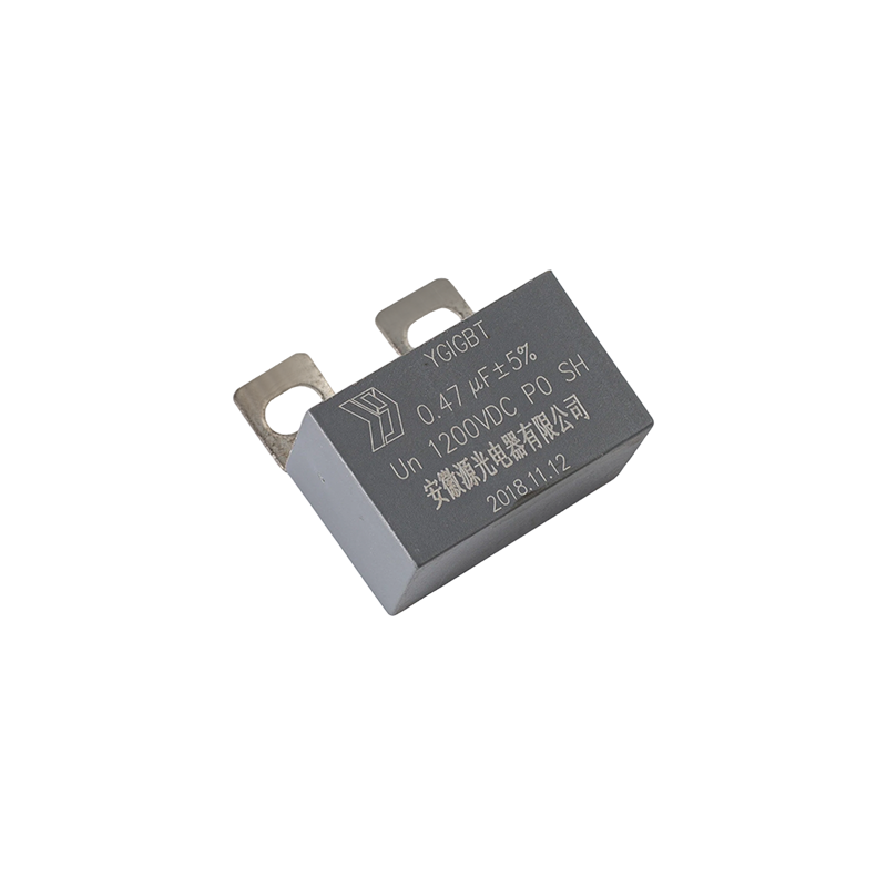 Metallized Polypropylene PCB AC Filter CapacitorsSelf-healing metallized polypropylene capacitors for small-power AC output filtering, including solar inverter LCL filters, with epoxy-filled UL94-V0 cases and voltage ratings up to 480 Vac.View Product →
Film Versus Aluminum Electrolytic: What the Choice Really Costs
For high-ripple, high-temperature duty, metallized polypropylene film is the more durable option, while aluminum electrolytic stays cheaper per joule of stored energy and remains the practical choice for bulk smoothing.
Metallized polypropylene film
- Self-healing: a breakdown vaporises the thin metal layer and isolates the spot
- High ripple current rating with stable ESR over life
- Non-polarised, tolerant of reverse voltage
- Dry or oil-immersed construction, no electrolyte to dry out
- Life figures commonly quoted at 100,000 hours
- Larger per microfarad and higher cost per unit
Aluminum electrolytic
- Highest energy density per unit volume
- Lower cost and wider stock availability
- Polarised, reverse connection causes failure
- Electrolyte evaporates over time
- Life roughly halves for every 10 °C rise in core temperature
- Best suited to bulk storage and low-frequency smoothing
Film wins on ripple current and life when the bus is hot and the switching frequency is high. Electrolytic wins on cost and volume when the ripple is modest and the enclosure has room. Many designs use both: electrolytic for bulk energy, film close to the switches for the high-frequency component.
Eight Specifications to Verify Before You Release a Purchase Order
Two capacitors with identical capacitance and voltage markings can differ by a factor of four in ripple current rating, so the purchase checklist has to go past the headline numbers.
- Voltage rating type. Continuous, peak, and surge ratings are three different figures. Confirm which one the quoted value refers to.
- Capacitance tolerance. Plus or minus 5 percent versus plus or minus 10 percent shifts a resonant point more than it shifts steady-state behaviour.
- Ripple current at frequency. A rating quoted at 50 Hz tells you little about 20 kHz. Ask for the derating curve.
- Hot-spot versus ambient temperature. The gap between them is often 15 to 25 °C and it decides your life calculation.
- ESR and ESL. Critical for snubber and high-frequency filtering duties where inductance dominates the response.
- Life rating conditions. A 100,000 hour figure is meaningless without the temperature and voltage attached to it.
- Case material and mounting. Aluminium, plastic, and stainless steel housings conduct heat very differently.
- Failure mode and safety class. For lighting and motor applications, the behaviour at end of life matters as much as the electrical performance.
Thermal margin decides the answer. In most field failures, the part was inside its voltage rating and outside its ripple current or hot-spot limit. A capacitor run at 80 percent of rated ripple current typically reaches its quoted life; at 120 percent, the same part may deliver less than half of it.
A Six-Step Selection Sequence That Works in Practice
Start from the waveform, not the catalogue. Working backwards from a datasheet page tends to lock in the wrong part before the requirements are known.
- Capture the real voltage and current waveform at the intended mounting point, including switching edges.
- Calculate RMS ripple current and identify the dominant frequency component.
- Convert that current into an expected hot-spot temperature using the supplier's thermal data.
- Compare predicted life against the service target of the equipment, not against a generic standard.
- Check mechanical fit: terminal spacing, case height, mounting orientation, and airflow around the housing.
- Run a small batch through thermal cycling before committing to volume purchase.
What Manufacturing Depth Changes About the Answer
A capacitor is only as good as its film, and a supplier who metallizes film in-house controls more of the failure modes that matter.
Metallized polypropylene film is made by vacuum-depositing a thin aluminium or aluminium-zinc layer onto a dielectric web. The deposition pattern, the margin width, and the zinc-to-aluminium ratio all determine how a self-healing event behaves, and how quickly ESR drifts over thousands of hours. Manufacturers who buy film on the open market accept whatever those parameters happen to be, which is why two capacitors with the same nameplate can behave very differently in service.
Film capacitor production at our plant has run continuously since 1995, with the product line never extended beyond capacitors and capacitor-grade metallized film. A 110 °C HID lighting capacitor was recognised as a provincial high-tech product in 2004 and as a national key new product in 2005, the same year the company joined the drafting work for GB/T 3667.1, the national standard covering performance, test methods, ratings, and safety requirements for AC motor capacitors.
More on the manufacturing and quality capability behind these product families covers the film coating, winding, and testing stages that sit between raw polypropylene and a finished part.
Frequently Asked Questions
What is the difference between a power capacitor and a motor run capacitor?
A motor run capacitor is one application of a power capacitor. It stays permanently connected across an auxiliary winding, so its ratings emphasise continuous AC voltage, low losses, and a defined failure mode. General power capacitors cover the wider set of duties such as DC-Link buffering, PFC, filtering, and snubbing, and are specified primarily on ripple current and hot-spot temperature.
How do I size a capacitor for power factor correction?
Start with the reactive load you want to offset in kvar, then match step size to how the load varies through the day. A motor that runs at 30 percent load most of the time needs several small switchable steps rather than one large block. Check the harmonic spectrum before specifying, because above roughly 10 percent THD a detuned reactor is needed to protect the capacitor from overcurrent.
How long do film power capacitors last?
Most metallized polypropylene power capacitors are quoted at 100,000 hours or more, but that figure assumes the stated hot-spot temperature and rated voltage. Running 20 °C hotter, or at 120 percent of rated voltage, shortens life substantially. The number worth asking a supplier for is the predicted life under your actual ripple current and ambient conditions.
Can power capacitors be mounted directly on a PCB?
Yes. PCB-mount metallized polypropylene parts are common for AC filtering and lower-power DC-Link duties, with pin spacing typically between 10 mm and 37.5 mm. The constraint is thermal: a board-mounted part has less surface area to shed ripple-current heat, so its usable ripple current is lower than the equivalent capacitance in a stud-mount aluminium case.